Gear drives are usually assembled and tested at the manufacturing plant. Gearboxes of low and medium power are sent from the manufacturer sealed. Powerful gearboxes, as well as open gears with large gears, are supplied disassembled for installation.
All machined gears are divided into 12 degrees of precision. Most often used for dairy industry equipment cylindrical gears 6-11th degree of accuracy, bevel 6-11th and worm 5-9th degree of accuracy (the lower the degree number, the higher the accuracy of the gear, determined by the standards of kinematic accuracy, smooth operation and tooth contact).
When assembling gears, it is necessary to check the radial and axial runout gear wheels, center-to-center distance, side clearance and degree of contact of the working surfaces of the teeth.
The radial and axial runout of cylindrical gears is checked on special prisms before installation or in the centers after mounting on the shaft. The runout is controlled with a thickness gauge or indicator (Fig. 7.8). To do this, a cylindrical gauge with a diameter of 1.68/u (where m is the module) is placed between the teeth of the wheel, on which the indicator leg is installed and the position of its arrow is fixed. By shifting the gauge through 2-3 teeth and turning the shaft, determine the difference in the indicator readings for the entire gear. This difference is the amount of radial runout along the initial circle of the gear. The axial runout is checked with an indicator.
The lateral clearances in the meshing of cylindrical gears are controlled with a feeler gauge or indicator (Fig. 7.9). To do this, a driver is attached to the shaft of one of the gears, the end of which rests against the leg of the indicator mounted on the body of the unit. The other wheel is fixed motionless with a clamp. The driver, together with the shaft and wheel, is turned in one direction, then in the other (this can only be done by the amount of the side gap). The difference in the indicator readings at the first and second position of the gear is recalculated to the value of the lateral clearance using the formula
Sp = CR 1L,
Where cn is the amount of side clearance, m; WITH - difference in indicator readings at the first and second positions of the gear wheel, m; R - radius of the initial circle, m; L - leash length, m.
IN technical conditions fix the smallest side gap.
|
|

When assembling gears with wheels whose modulus is higher than 6 mm, these gaps are checked by rolling between the teeth
three or four pieces of lead wire installed along the length of the tooth.
Wire impressions are strips of variable thickness. The smaller thickness c corresponds to the part of the side gap on the working side of the tooth, and the larger thickness c2 corresponds to the non-working side. The sum of these quantities is the lateral clearance, i.e. cn = c + c2.
Finish checking the gearing by inspecting paint prints at the contact points. To do this, the teeth of the drive gear are coated with a thin layer of soot or blue, diluted in drying oil, and the gear train is turned several times.
Touch marks (prints) appear on the teeth of the driven wheel, by which the quality of the engagement is judged. If the impressions are in the upper part of the tooth, then the center-to-center distance is greater than normal. When making an impression on the bottom of a tooth, the wheels are brought closer together than necessary. In a correctly assembled gear, the prints are located in the middle part of the side surface of the teeth in height and length.
If there is insufficient contact between the tooth surfaces, finishing during installation is carried out by scraping, grinding in with abrasive powders and pastes, and grinding in with oil under load. The use of files is strictly prohibited.
Bevel gears are mainly assembled during repairs. In this case, the vertices of the initial cones must coincide, and the axes must be mutually perpendicular. Deviations in engagement should not exceed tolerance limits. The position of the axes of the bevel gears is verified using strings with plumb lines, rulers and other universal tools. The installation of bevel wheels is checked by the coincidence of their forming wheels in the plane of the axes of the wheel. The permissible deviation is 0.1-0.5 mm. When checking for paint, it is detected following deviations from the norm: insufficient clearance - the wheels are too close together (Fig. 7.10, d); the interaxial angle is smaller (Fig. 7.10, V) or more than calculated (Fig. 7.10, 6). If on the teeth of the driving or driven wheels traces of paint are located densely on one side of the tooth at the narrow end, and on the other side at the wide end, this indicates that the axes of the gear wheels are misaligned. In all cases, deviations from the norm are corrected by additional plumbing operations. Typical prints when bevel wheels are properly engaged are shown in Fig. 7.10, A.
Rice. 7.10. Bevel gear engagement quality control:
I - no load (during assembly); II - with full load (in operation); a - correct engagement; b - the interaxial angle is greater than the calculated one; c - the inter-axial angle is less than the calculated one; g - insufficient clearance
When assembling a worm gear, check the center-to-center distance of the worm shafts and the worm wheel, the correct position of the shafts, the lateral clearance in the mesh and the fit of the working surfaces of the wheel teeth and worm turns. The installation of the worm pair is checked using specially made templates and probes, plumb lines, a scale ruler and a level. Plumb lines are lowered from the worm shaft and the distance from the shaft to the side surface of the wheel is measured. If the gearing is correct, these distances should be the same. Such a check cannot always be carried out, since the gear is installed in the gearbox housing. Therefore, during installation, check the contact with paint (Fig. 7.11). A touch shift to one side or the other indicates a misalignment of the axes. The approach of the contact spot to the edge of the tooth indicates an increased interaxial distance, and vice versa.
Rice. 7.11. Worm gear engagement quality control
For normal operation In a worm gear, the amount of lateral clearance is of great importance (Fig. 7.12), which depends on the accuracy and size of the gear. In assembled gears, the amount of clearance is determined by the rotation of the worm during a “dead” motion, i.e., with angular movement of the worm and a stationary wheel. If this gap is absent, the worm jams.
In small-sized precision gears, where the lateral clearance is very small, the free rotation of the worm is determined by an indicator. At the protruding ends of the worm and wheel, levers are attached that touch the indicators, and the position of the indicator arrow is fixed in the initial position.
Meshing defects contribute to the appearance of additional sounds and noises: knocking and clicking of teeth, sometimes disappearing, sometimes intensifying, can be caused by tooth pitch errors or too large gaps; rattling sounds and grinding noises, entailing vibration of the transmission housing, can be caused by small side clearances (tight engagement), the presence of sharp edges on the heads of the wheel teeth, and misalignment of the wheel axles; noise high tone, which turns into a sharp howl and constant uneven knocking in the meshing with increasing rotation speed, occurs when the shape of the working surfaces of the teeth is distorted or the presence of local defects on them; periodically increasing and weakening noise, systematically repeated with each revolution of the wheel, is a consequence of the eccentric arrangement of the teeth relative to the axis of rotation or a loose fit.
The normal operation of a worm gear is determined by testing it idle and under load. At the same time, not only the size and nature of the contact spots are checked, but also the heating temperature of the gear, which should not exceed 80 °C for gears of the 2nd and 3rd degrees of accuracy, and 65 °C for gears of the 4th degree of accuracy. Excessive heat indicates defective assembly and workmanship, insufficient lubrication or improper selection of lubricating oil.
The lateral gap j n between the idle tooth profiles of mating wheels is determined in a section perpendicular to the direction of the teeth, in a plane tangent to the main cylinders (Figure 36). This gap is necessary to eliminate jamming when the gear is heated (temperature compensation), to accommodate a layer of lubricant, and also to compensate for manufacturing and assembly errors. The lateral clearance leads to the appearance of backlash when reversing gears, the magnitude of which is limited to reduce impacts on non-working tooth profiles. The theoretical gear transmission is two-profile and backlash-free (j n = 0). The actual transmission should have side clearance.
The minimum value of the lateral clearance j n min determines the type of tooth mating. The standards provide for six types of mating: A (with an increased guaranteed gap j n min for 3-12 degrees of accuracy), B (with a normal guaranteed gap, 3-11), C, D (with a reduced j n min, 3-9, 3-8 ), E (with small j n min , 3-7), N (zero j n min , 3-7).
Eight types of tolerances Tj n for side clearance have been established (in this case Tj n =
j n min - j n max): h, d, c, b, a, z, y, x. Tolerances are arranged in ascending order. The types of conjugation H and E correspond to the tolerance type h, the types of conjugation D, C, B, A correspond to d, c, b, a, respectively. It is allowed, for technological or other reasons, to change the correspondence of mating types and lateral clearance tolerances, also using tolerance types z, y, x (see Figure 36).
Six classes of deviations of interaxial distances have been established, designated in descending order of accuracy by Roman numerals from 1 to Y1. Guaranteed lateral clearance is ensured subject to compliance with the classes of deviations of the interaxial distance established for this type of mating (H, E – II class, D, C, B, A – III, IY, Y, YI classes).
The minimum lateral clearance j n min must take into account the temperature compensation j nt and the lubricant layer cm:
j n min = j nt + see (3.156)
Figure 36 – Lateral clearance in gear transmission
The required temperature compensation can be calculated by knowing the temperature of the wheel t wheel and gear housing t lane and taking into account that the side clearance j n is measured at the profile angle :
t = a w [ count (t count – 20 0) - cor (t corr – 20 0)],
where w is the interaxle distance, I are the linear expansion coefficients ( number - wheels, core - body).
Considering that the thickness of the lubricant should be from 0.01 to 0.03 module, we obtain that the minimum (guaranteed) lateral clearance j n min should be equal to
j n min = (0.01 0.03) m + a w [(( count (t count –20 0) - lane (t lane – 20 0) 2sin (3.157)
Type B coupling guarantees lateral clearance, which prevents jamming of gear teeth from heating when the temperature difference between the wheels and the housing is 25 0 C (see Figure 36).
As follows from the above, the type of tooth mating is determined by calculation or experiment, regardless of the degree of accuracy. Permissible errors in the manufacture or installation of a gear, depending on the degree of accuracy, affect the maximum value of the side clearance.
There are three methods for ensuring lateral clearance: adjusting the distance between the gear axes, using a special tool with thicker teeth in the manufacture, and the method of radially shifting the original contour of the gear cutting tool rack.
The first method is practically not used, because moving the working shafts to obtain lateral clearance leads to a decrease in the active part of the profile and the overlap coefficient; This method is not possible with several pairs of mating teeth sitting on two parallel shafts, since the adjusted side clearance of one pair of gears gives unacceptable values for the remaining pairs of gears.
The second method of obtaining “thin” gear teeth by increasing the thickness of the cutting teeth of the tool (mills, racks, etc.) leads to an increase in the range and rise in price of the tool.
The third method has become predominantly widespread, since it uses a standard tool and allows for any lateral clearances due to the additional displacement of the gear cutting tool into the “body” of the workpiece. The smallest lateral gap is created by reducing the tooth thickness along a constant chord E with the method of radial displacement of the original contour by the amount E N. An additional reduction in the tooth thickness along the chord by the tolerance value T c occurs due to the tolerance for the displacement of the original contour T N, which causes a corresponding increase side clearance. Dependencies characterizing the change in the lateral clearance from the displacement of the original contour and tooth thinning are shown in Figure 36:
j n min = 2 E N sin; (3.158)
E C = 2E H tg. (3.159)
Thus, the lateral clearance is determined by the displacement of the original contour E H, the center distance A(deviations f a are set for it), tooth thickness on the pitch circle or constant chord of the tooth 
In the presence of radial runout F r, the tooth thicknesses do not remain constant, but change with approaching and moving away from the drive wheel, therefore T H F r:
T H = 1.1 F r + 20. (3.160)
The side clearance consists of the guaranteed side clearance j n min and the side clearance j n 1 to compensate for manufacturing and installation errors (1 and 2 – wheel and gears):
j n min + j n1 = (E H 1 + E H 2)2 sin. (3.161)
Assuming the wheel and pinion offsets are approximately the same
E N 1 E N 2 E N, we get ( = 20 0):
The lateral clearance j n 1 takes into account the deviations of the interaxle distance fa, the engagement pitch f p in two wheels, the deviation of the direction F of two wheels, the deviation from parallelism f x and the misalignment of the axes f y, j n 1 is equal to quadratic summation:
The largest lateral gap is the closing link of the assembly dimensional chain, the component links of which will be deviations of the center distance and displacements of the original contours:
j n max = j n min + (T H 1 + T H 2 + 2f a) 2sin. (3.164)
Taking into account production needs, the following indicators are used to characterize the side clearance:
the smallest displacement of the original contour E N (tolerance T N );
smallest deviation of tooth thickness E WITH (tolerance T WITH = 0.73 T N );
smallest deviation of average length common normal E wm (tolerance T wm );
the smallest deviation of the length of the common normal E w (tolerance T w );
maximum deviations of the measuring center distance E a`` (+ E a `` s and -E a`` I ).
Normal W is the distance between opposite side surfaces of a group (2, 3, etc.) of teeth.
Measuring center distance – the distance of backlash-free mating of the teeth of the controlled wheel and the measuring wheel; E a `` s =  (fluctuation of the measuring distance on one tooth); E a `` I = -T N.
When developing drawings of gear wheels, gearbox housings, drives, etc. indicators w (E w , T w), S c (E c , T c), f a are used (Figure 36).
When monitoring gears, sets of indicators are used that are established for various degrees of accuracy. Control complexes are equal, but not equivalent. The first of them (for each standard, formed by one complex indicator, gives the most complete assessment of the accuracy of the wheel). Each subsequent one characterizes a significant portion of the main error or its individual parts.
The choice of one or another control complex depends on the purpose and accuracy of gears and gears (inversion principle), their sizes, control practices, volume and production conditions, etc. For the selected complex, the necessary tolerances and deviations are indicated in the drawing of a gear with a non-standard initial contour and the wheel is controlled in all respects.
In the drawings of gears with a standard initial contour (Figure 37), the designer does not indicate the indicators of the complex; these indicators are assigned by technology services.
Inspection of gear wheels can be acceptance, preventive and technological.
Acceptance control – control the performance of the complex.
Preventive – debugging technological processes and identifying the causes of defects.
To control kinematic accuracy, instruments are used to measure the kinematic error of wheels, the measuring center distance, the accumulated error of steps, radial runout, fluctuations in the length of the common normal, and the rolling error.
When monitoring the smoothness of operation, instruments are used to measure local kinematic and cyclic errors, meshing pitch, profile error, and angular pitch deviations.
When monitoring the completeness of contact, instruments are used to measure the total contact patch, axial pitch, tooth direction, shape error and contact line location.
When monitoring the lateral clearance, the displacement of the original contour, the deviation of the measuring center distance, the deviation of the average length of the common normal, and the thickness of the tooth (including caliper gauges) are measured with instruments.

Figure 37 – Gear
To eliminate possible jamming when the gear is heated, to ensure conditions for the flow of lubricant and to limit the backlash when reversing the reference and dividing real gears, they must have a lateral clearance j n (between the non-working profiles of the teeth of the mating wheels). This gap is also necessary to compensate for errors in the manufacture and installation of the transmission. The lateral clearance is determined in a section perpendicular to the direction of the teeth, in a plane tangent to the main cylinders (Figure 8.2.13). Figure 8.2.13 Lateral clearance is provided by radially displacing the original contour of the rack (gear cutting tool) from its nominal position in the wheel body. The gear tolerance system establishes a guaranteed lateral clearance j nmin, which is the smallest prescribed lateral clearance, independent of the degree of accuracy of the wheels and gears. It is determined by the formula: where V is the thickness of the lubricant layer between the teeth; a ω - center distance; α 1 and α 2 – temperature coefficients of linear expansion of the material of the wheels and body; Δt° 1 and Δt° 2 – deviation of the wheel and body temperatures from 20°C; α is the profile angle of the original contour. The thickness of the lubricant layer is approximately taken to range from 0.01m (for low-speed kinematic gears) to 0.03m (for high-speed gears). To meet the requirements of various industries, regardless of the degree of precision in the manufacture of gear wheels, six types of interfaces are provided that determine different values of j nmin: A, B, C, D, E, H (Figure 8.2.14).  Figure 8.2.14 Six classes of center-to-center distance deviations have been established, designated in descending order of accuracy by Roman numerals from I to VI. The guaranteed lateral clearance in each mating is ensured subject to the prescribed classes of deviations of the interaxial distance (for matings H and E - class II, for matings D, C, B and A - classes III, IV, V and VI, respectively). The correspondence between the types of mates and the specified classes can be changed. The lateral clearance has a tolerance T jn, determined by the difference between the largest and smallest clearances. As the side clearance increases, the tolerance T jn increases. Eight types of tolerance T jn for lateral clearance are established: x, y, z, a, b, c, d, h. Types of mates H and E correspond to tolerance type h, types of mates D, C, B and A correspond to tolerance types d, c, b and a, respectively. The correspondence between types of mates and types of tolerances T jn can be changed using tolerance types z, y and x. The runout of the ring gear is defined as the difference between the highest and lowest indicator readings when the tip is located in all cavities of the controlled wheel.
Standardized parameters characterizing gear transmission are:
Tooth module,
Gear ratio,
Center distance.
Worm gears are classified as gear-screw gears. If in a gear-screw transmission the angles of inclination of the teeth are taken such that the teeth of the gear surround it around it, then these teeth turn into turns of thread, the gear into a worm, and the gear from a helical gear into a worm. The advantage of a worm gear over a helical gear is that the initial contact of the links occurs along a line rather than at a point. Crossing angle shafts worm and worm wheel can be anything, but usually it is 90°.
Bevel gear
If the angle between the axes is 90°, then the bevel gear is called orthogonal. In general, in a non-orthogonal transmission, the angle added to 180° to the angle between the angular velocity vectors of the links 1 And 2, called center angle Σ
33\34. Normalization of dimensional interaction parameters in keyed connections
KEYED CONNECTIONS
Purpose of keyed connections Keyed connections are designed to produce detachable connections that transmit torques. They ensure the rotation of gears, pulleys and other parts mounted on shafts along transitional fits, in which, along with interference, there may be gaps. The dimensions of the keyed connections are standardized. There are key connections with prismatic (GOST 23360), segment (GOST 24071), wedge (GOST 24068) and tangential (GOST 24069) keys. Keyed connections with prismatic keys are used in lightly loaded low-speed transmissions (kinematic feed chains of machine tools), in large-sized products (forging equipment, flywheels of internal combustion engines, centrifuges, etc.). Wedge and tangential keys absorb axial loads during reversals in heavily loaded joints. The most widely used are parallel keys. Design and dimensions of parallel keys Parallel keys have three designs. The type of key design determines the shape of the groove on the shaft. Execution 1 for a closed groove, for normal connection under serial and mass production conditions; version 2 for an open groove with guide keys, when the sleeve moves along the shaft with a loose connection; version 3 for a semi-open groove with keys installed at the end of the shaft with a tight connection of the pressed sleeve onto the shaft in single and serial types of production. The dimensions of the key depend on the nominal size of the shaft diameter and are determined according to GOST 23360. Examples of key designations: 1. Key 16 x 10 x 50 GOST 23360 (prismatic key, version 1; b x h = 16 x 10, key length l = 50). 2. Key 2 (3) 18 x 11 x 100 GOST 23360 (prismatic key, version 2 (or 3), b x h = 18 x 11, key length l = 100). Key fits and recommendations for selecting tolerance margins The main fit dimension is the width of the key b. According to this size, the key mates with two grooves: a groove on the shaft and a groove in the bushing. The keys are usually connected to the grooves of the shafts motionlessly, and to the grooves of the bushings with a gap. The interference is necessary to ensure that the keys do not move during operation, and the clearance is necessary to compensate for inaccuracies in dimensions and relative position of the grooves. Keys, regardless of fit, are manufactured to size b with tolerance h9, which makes their centralized production possible. The remaining dimensions are less important: the height of the key according to h11, the length of the key according to h14, the length of the groove for the key according to H15. The keys are seated according to the shaft system (Ch). The standard allows various combinations of tolerance fields for grooves on the shaft and in the bushing with a key width tolerance field. A loose connection is used to guide long keys; normal ones are most often used for fastening keys installed in the middle of the shaft; tight connection - for keys at the end of the shaft. Basic requirements for the design of cross-sections of a connection with a parallel key and the parts involved in them. Maximum deviations of dimensions and selected tolerance fields are determined according to the tables of GOST 25347. When making a cross-section of a keyed connection, it is necessary to indicate the fits, and for the key - the tolerance fields for dimensions b and h of the mixed key and surface roughness. In the drawings of the cross sections of the shaft and bushing, it is necessary to indicate surface roughness, tolerance fields for dimensions b, d and D in a mixed form, as well as normalize the dimensions of the depth of the grooves: on the shaft t1 - the preferred option or (d - t1) with a negative deviation and in the bushing (d + t2) – the preferred option or t2 with a positive deviation. In this and other cases, the deviations are selected depending on the height of the key h. In addition, in the drawings of the transverse sections of the shaft and bushing, it is necessary to limit the accuracy of the shape and relative position to tolerances. Requirements are made for permissible deviations from the symmetry of the keyways and the parallelism of the plane of symmetry of the groove relative to the axis of the part (base). If there is one key in the connection, the parallelism tolerance is taken equal to 0.5IT9, the symmetry tolerance is 2IT9, and with two keys located diametrically, it is 0.5 IT9 from the nominal size b of the key. Symmetry tolerances may vary in high volume and mass production.
Cylindrical gears. Transmission by spur gears is carried out from the upper crankshaft to the camshafts of the fuel pumps and to the blower, from the lower crankshaft to the oil and water pumps. In addition, the oil pump has two pairs of spur gears: straight and chevron teeth.
The normal operation of a gear transmission largely depends on the clearance between the gear teeth. When identifying malfunctions in the operation of the gear train, it is necessary to first check the gaps between the gear teeth. These gaps are checked using an indicator, the leg of which is pressed against the working surface of one of the teeth. The difference in the indicator readings when the gears rock will correspond to the actual gap between the teeth. After disassembling the drive, as well as when replacing individual gears or bearings, it is necessary to check and, if necessary, adjust the engagement of the gears (lateral clearance between the teeth, as well as the fit of the teeth according to the paint print).
Adjusting the gear engagement of the oil and water pumps. Gaskets 1 (Fig. 166), which are placed under the flange of housing 2, regulate the size of the gaps between the teeth of gears 4 and 3 of the oil pump drive. For diesel engines produced since 1961, in which the speed regulator is installed on the left side, the engagement of the cylindrical gears of the oil pump drive is adjusted with shims /1 (see Fig. .120). For new gears, the gaps should be within 0.24-0.4 mm, and for used ones, no more than 0.55 mm. Stepping of the ends of the teeth of paired gears is allowed up to 2 mm. To make it easier to adjust the gaps, the gaskets are made with a thickness of 0.2; 0.3 and 0.75 mm.
When checking the fit of the teeth, the paint imprint on each tooth must be at least 50% of the length and at least 50% of the height of the tooth. Having adjusted the gear engagement, drill two holes for pins 14 in the drive housing and in the block and deploy them together.
Adjustment of the gaps between the teeth of gears 4 and 5 of the water pump drive within 0.2-0.4 mm is carried out by moving the housing (plate) in which the pump is mounted relative to the diesel unit. The contact of the teeth with the paint must be at least 40% along the height of the tooth and at least 50% along its length.
The gearing of the centrifugal filter oil pump drive gears is adjusted in the same way. After adjusting the gear engagement of the water and oil pumps, the gear spacing should not exceed 2 mm.
The gaps between the gear teeth are set within 0.1-0.3 mm for any pair of new gears and no more than 0.55 mm for working gears. Fluctuations in clearance values for one pair of gears should not exceed 0.1 mm. The quality of gear engagement is checked by the fit of the teeth. The paint imprint must be at least 50% along the height of the tooth and at least 60% along its length, with the imprint located in the middle part of the tooth. The pitch of all drive gears should not exceed 2 mm. If it is necessary to reduce the gear spacing between brackets 8 and the diesel block, install steel spacers.
Adjusting the gear engagement of the blower drive. Whenever installing a blower on a diesel engine, replacing drive gears or the blower itself, it is necessary to adjust the engagement of its drive gears. When properly meshed, the gaps between the gear teeth are in the range of 0.1-0.25 mm for new gears and do not exceed 0.4 mm for used gears. The contact area of the teeth based on the paint imprint is at least 50% of the height and at least 60% of the length of the tooth. The gear pitch does not exceed 2 mm.
The engagement is adjusted by moving the blower on the pins that secure it to the block. Such movement is carried out only after smooth engagement! gears 1 and 2 (Fig. 167) and preliminary check of engagement. It is allowed to drill or saw a hole in the blower (for the passage of studs) if the existing holes do not allow its movement. The lateral clearance between the gear teeth is checked as follows. Carefully rotate the driven coordination gear 4 until the teeth of gears 1 and 2 stop and in this position set the indicator scale to zero. Then rotate gear 4 in the opposite direction, also until the teeth of gears 1 and 2 stop. Based on the indicator reading, the actual size of the gap is determined.
Adjusting the mesh of the blower coordinating gears. Blower timing gear engagement must be monitored when replacing gears, rotors or bearings. Coordination gears are selected and run in to each other during their manufacturing process. Therefore, these gears need to be replaced only as a complete set.
The meshing of the blower coordinating gears must satisfy the following requirements.
1. The lateral clearance between the teeth of new gears should be in the range of 0.05-0.2 mm and up to 0.35 mm for old ones. Fluctuation of clearances for one pair of gears is allowed up to 0.1 mm.
2. The contact of the gear teeth with paint must be at least 60.% along the tooth length and at least 50% along the tooth height.
3. The discrepancy between the outer ends of the gears (by teeth) is allowed no more than ± 1 mm.
Adjusting the gear engagement of the oil pump. When replacing oil pump gears (synchronous or herringbone), it is necessary to monitor the engagement of their teeth.
The total gap between the teeth of the chevron gears pressed to one end of the pump should be in the range of 0.10-0.15 mm. The gap size is determined by selecting gears. In this case, the driven synchronous gear 5 (see Fig. 43) must be strengthened with a pin so that the lateral gap on each side of the chevron gear tooth is at least 0.05 mm, and the gap in the synchronous gears is chosen in the direction of its reduction.
The lateral clearance between the teeth of synchronous gears should be in the range of 0.03-0.15 mm for new gears and no more than 0.25 mm for used gears. The gap size is determined by selecting gears. The teeth of synchronous gears are also checked by paint marks, which must be at least 65% along the tooth height and at least 70% along the tooth length.
The gaps between the gear teeth of the high-performance oil pump are not adjustable, but only monitored. The quality of gear engagement is ensured by the manufacture of the pump and gears. The lateral gap between the teeth should not exceed 0.55 mm.
Bevel gears. Gears with bevel teeth are installed on a vertical gear, on drives to the speed controller and tachometer.
The quality of engagement between gear teeth must be checked during each lifting repair of a diesel locomotive, when any malfunctions occur in the transmission, when replacing gears, bearings or other parts, as well as after disassembling the gear transmission. For each pair of gears, check the fit of the teeth against the paint and the size of the lateral gaps between the teeth.
The lateral gaps between the teeth are checked using an indicator, and the quality of the fit is checked by paint, the same as for gears with cylindrical teeth.
Adjusting the engagement of vertical gears. Before checking, you need to make sure that ring 16 is selected correctly (see Fig. 119), which determines the preliminary value of the lateral clearance between the gear teeth. For new gears, the side gaps between the teeth should match the gap set at the factory and marked on the end of one of the teeth of the large gear. In practice, the clearances should be in the range of 0.3-0.55 mm (up to 0.7 mm for running gears) with the selected crankshaft run towards increasing the clearance and at least 0.2 mm (0.1 mm for running gears) with the selected run-up in the direction of decreasing the gap. In this case, the fluctuation of clearances for one pair of gears should not exceed 0.25 mm.
To check the fit of the teeth against the paint, the teeth of the small gear are coated with a thin layer of glaze (paint) and then the gear is turned several revolutions, first in one direction and then in the other direction. In this case, the crankshaft run-up should be chosen in the direction of decreasing the clearance.
The length of the paint print on the convex side of the large gear tooth must be at least 50 mm, and on the concave side 35 mm. The prints should be located in the zone of the pitch, cone, and along the length - somewhat closer to the top of the tooth; It is allowed to place the imprint closer to the base, provided that the length of the imprint is at least 70 mm on the convex side and at least 50 mm on the concave side of the tooth. The print can be in the form of a continuous spot or in the form of two separate spots with a gap of up to 6 mm in length. The beginning of the imprint should be no more than 5 mm from the top of the tooth.
If the print is unsatisfactory, as well as if it is necessary to change the gap between the teeth, the engagement of the gears is adjusted by their axial movement due to gaskets placed under the flanges of large gears and vertical shaft housings. Gaskets placed under the large gear flange are made in the form of half rings with a thickness of 0.1 and 0.25 mm, and gaskets under the vertical shaft housing are made in the form of plates with a thickness of 0.1; 0.25 and 1 mm.
Adjusting the gearing of the drive gears regulates the speed. The gaps between the gear teeth should be within 0.1-0.2 mm for new gears and no more than 0.4 mm for used gears. When measuring the gap values, it is necessary to select possible runs in each pair of gears as follows: for one of the gears, select the run in the direction of increasing the gap, and for the other, in the direction of decreasing it. When checking the meshing of gears for adherence to the paint, the imprint must be at least 50% of the length of the tooth. The required gap between the teeth and the fit of the teeth are ensured by the selection of shims. Stepping of the ends of the gear teeth is allowed up to 2 mm.
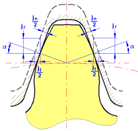
Types of side clearances (defined for each gear in a gear set)
Actual gears must be manufactured with specific permissible flank clearances. Define valid values, based on your working conditions.
In spur and helical gears, there are two ways to determine the required flank clearance. First, reduce the tooth thickness by immersing the punch in the empty mold to a depth greater than what the standard would theoretically allow. Secondly, increase the center distance compared to the theoretically calculated one.
When setting side clearance, consider the following factors:
- Space required for lubrication.
- Differential expansion between gear components and housing.
- Errors in calculations. Insufficiency of both wheels, profile errors, pitch, tooth thickness, tooth angle and center distance. The smaller the side clearance, the more accurate the gear machining will be.
- Operating conditions such as frequent reversing or excessive load.
The side clearance size should not be too large to meet the job requirements. Make sure it is sufficient to ensure that machining costs do not exceed what is necessary.
Traditionally, half the flank clearance tolerance value is set for the tooth thickness of each gear in a pair. However, there are exceptions. For example, gears that have a small number of teeth use all the valid values for the driven gear. As a result, there is no weakening of the gear tooth.
- Circular side clearance j t [mm/inch]
- Normal side clearance j n [mm/in]
- Center side clearance j r [mm/in]
- Angular side clearance j Θ [grad]
| Types of gear engagement | Relation between circular direction j t and normal direction j n | Relation between circular direction j t and central direction j r | The relationship between the circumferential direction j t and the angular side clearance j Θ |
|---|---|---|---|
| Spur gear | j n = j t cos α | ||
| Helical spur gear | j nn = j tt cos α n cos β |
|
|
|

Lateral clearance of helical gear engagement
For helical gears, there are two types of side clearances related to the tooth spacing. There is a cross section in the normal direction of the tooth surface “n” and a cross section in the direction perpendicular to the “t” axis.

|
j nn |
Lateral clearance in a direction perpendicular to the tooth surface |
|
jnt |
Lateral clearance in the circumferential direction in a cross section perpendicular to the tooth |
|
j tn |
Lateral clearance in a direction perpendicular to the tooth surface in a cross section perpendicular to the axis |
|
j tt |
Lateral clearance in a circular direction perpendicular to the axis |
|
In the plane normal to the tooth: |
j nn = j nt cos α n |
